When you make purchases through links on this site, The Track Ahead may earn an affiliate commission. Also, these posts are based off my own experiences. I am not responsible for any action you take as a result of reading this. Learn More
Since I’ve been remodeling the garage in our home, I’ve had new drywall installed and gone through the steps to prep and paint the walls. Prior to getting the walls up, I knew I would have the opportunity to run a new electrical circuit and install some outlets so that I charge and plug in my tools. I also planned to install a wall-mounted garage door opener near the garage door, which I would need to run electrical and provide an outlet for.
I’ve done a lot of electrical work in the past and have familiarized myself with many of the building codes and electrical codes in my locale, so I felt comfortable working on this project. I understand that not everyone may be as familiar with the various codes and with handling of residential electrical wiring; if that is the case for you, I would advise having a qualified electrician do the work for you. For those who are comfortable working with electricity and understand the local codes required for electrical work on their home, I’ve detailed my install below based on my own experience in the hopes that it helps you with your very own project.
Tools & Materials Used
For your specific project, size up the electrical wire based on what amperage you need. In my situation, this circuit will be in the garage for general use, but also for times where I’ll need to plug in power tools that will draw more amperage.
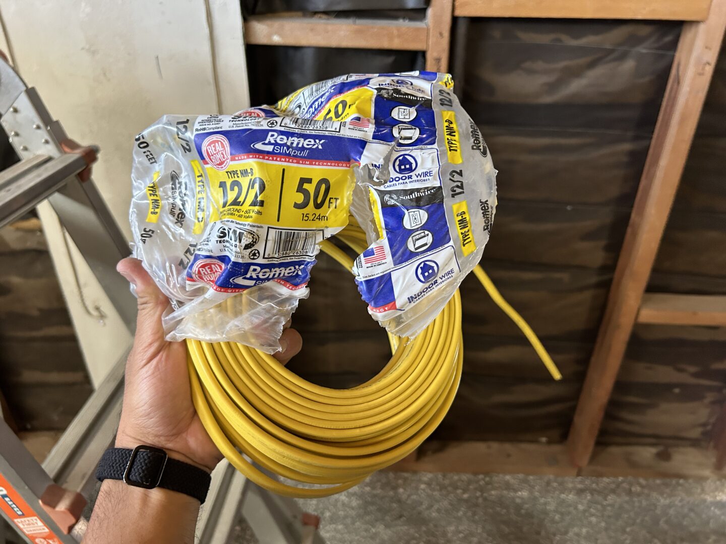
Therefore, I ran a typical Type NM (Non-Metallic Sheathed) cable: 12/2 Solid Romex to various 20-amp outlets on this circuit. I went with 12/2 cable to match the amperage of the outlets. Generally the 14/2 Solid Romex goes with your typical 15-amp outlets.
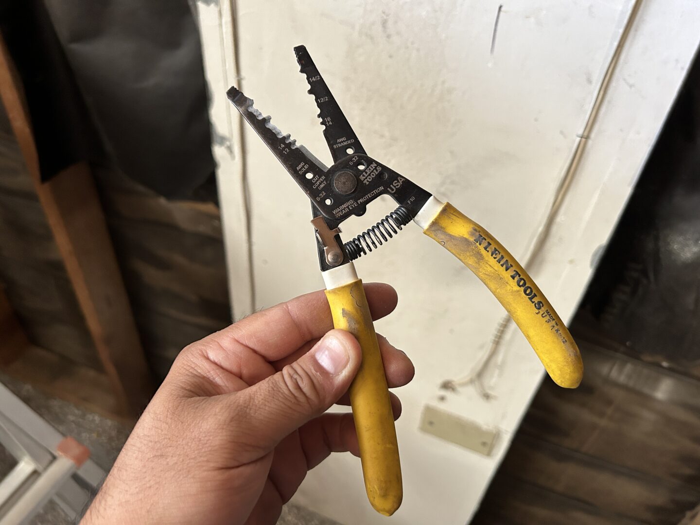
I also used wire strippers to make connections, 20-amp outlets(wall plates), and wire clamp connectors, receptacle boxes, and 20-amp circuit breaker.
GFCI (ground fault circuit interrupter) outlets are required where a water source is present. This generally applies to bathrooms, kitchens, and garages. Depending on your local codes, GFCI’s may be required on all outlets in your garage. Installing regular outlets downstream of your upstream GFCI outlet may be allowed as well. If you want to play it safe and don’t mind the extra cost, install GFCI’s on all outlets.
Type NM Cable (12/2 Romex): 15ft / 25ft / 50ft / 100ft
Wire Strippers
20-amp Outlets / GFCI Outlets / Wall Plates
20-amp Circuit Breaker
New Construction Single-Gang Outlet Boxes
Wire Clamp Connectors

Other tools I used for this project include:
Hammer
Screwdriver Set
Power Drill
Spade Drill Bits
Righ Angle Drill Attachments
Stud Plates
Electrical Staples
Fireblock Material
How to Add and Install New Electrical Outlets
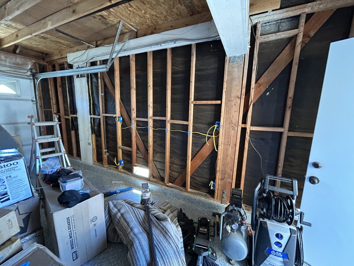
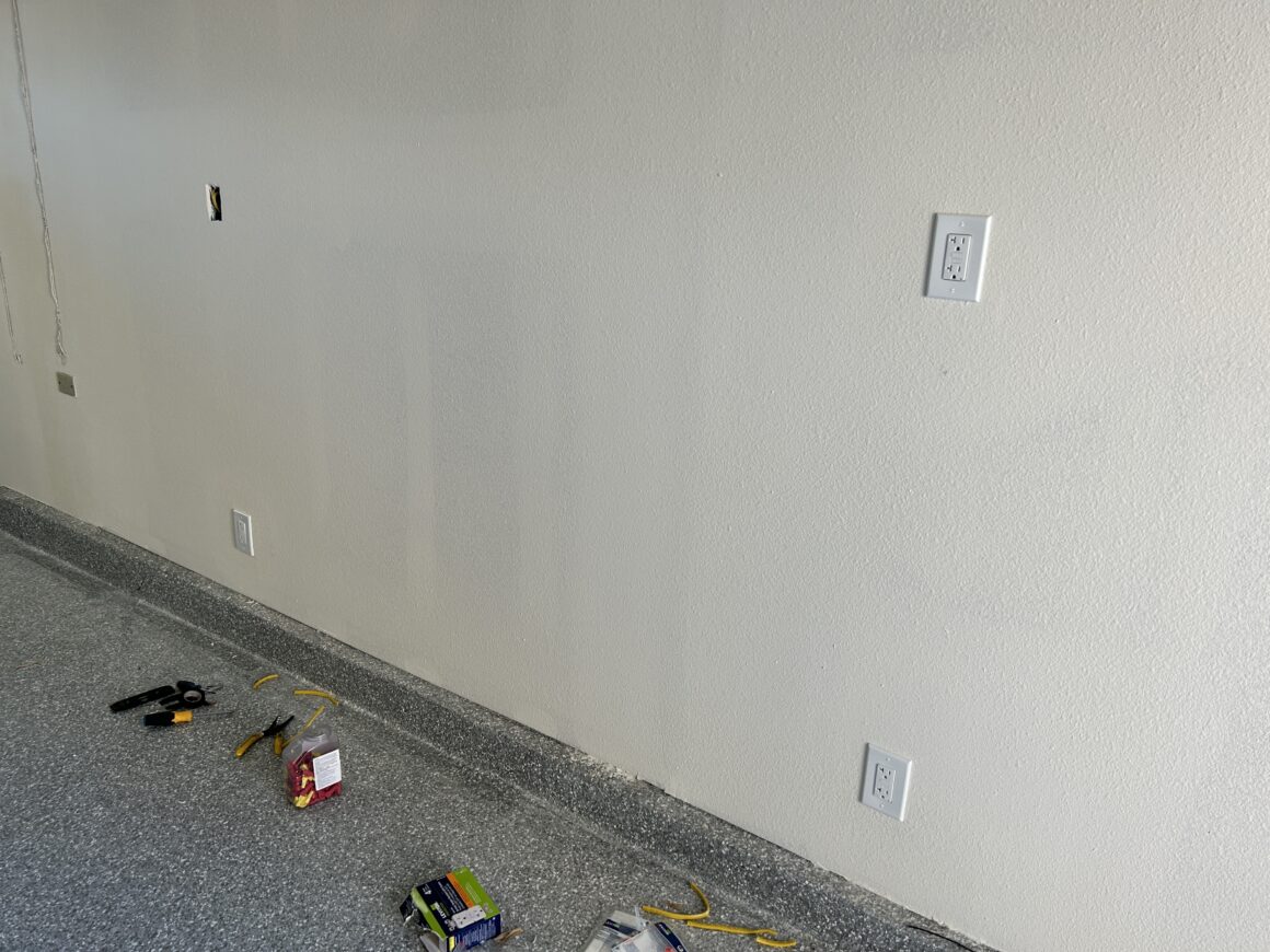
This is the unfinished wall that I started off with in our garage. I plan to install insulation and drywall, so this is the best time to install new electrical because you can run everything very easily without having to fish and run wires behind existing drywall.

At this stage, you should plan your run and decide where you want to install the new electrical outlets. The new electrical wiring will need to run through the existing studs (and might be able to be installed through the attic space if it is a non-living space).
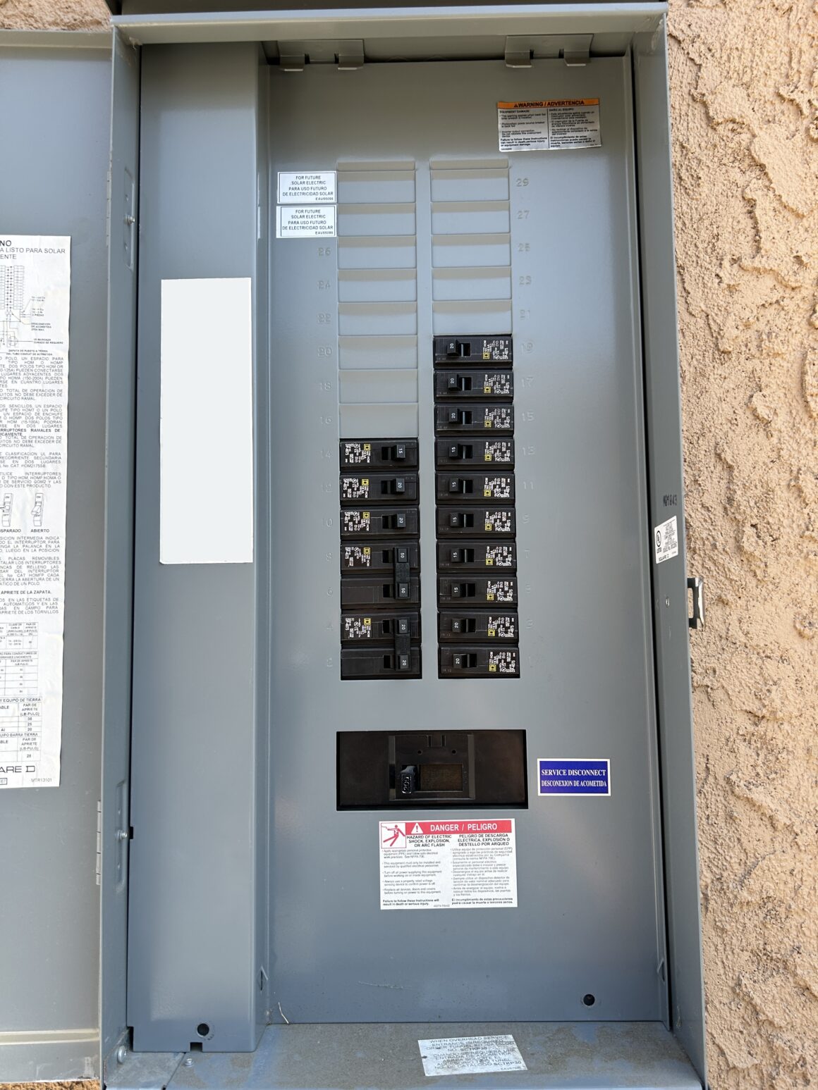
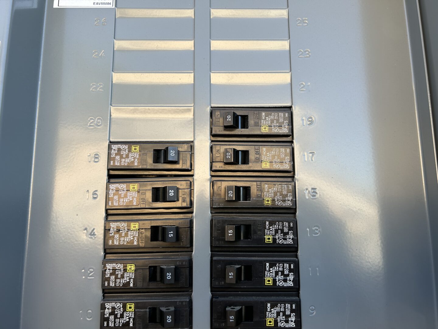
On the main panel, you should check to see if you have a space for a new circuit breaker. To minimize disruption to the power in your home, first run the wiring on the inside of the garage prior to doing any work at the panel.
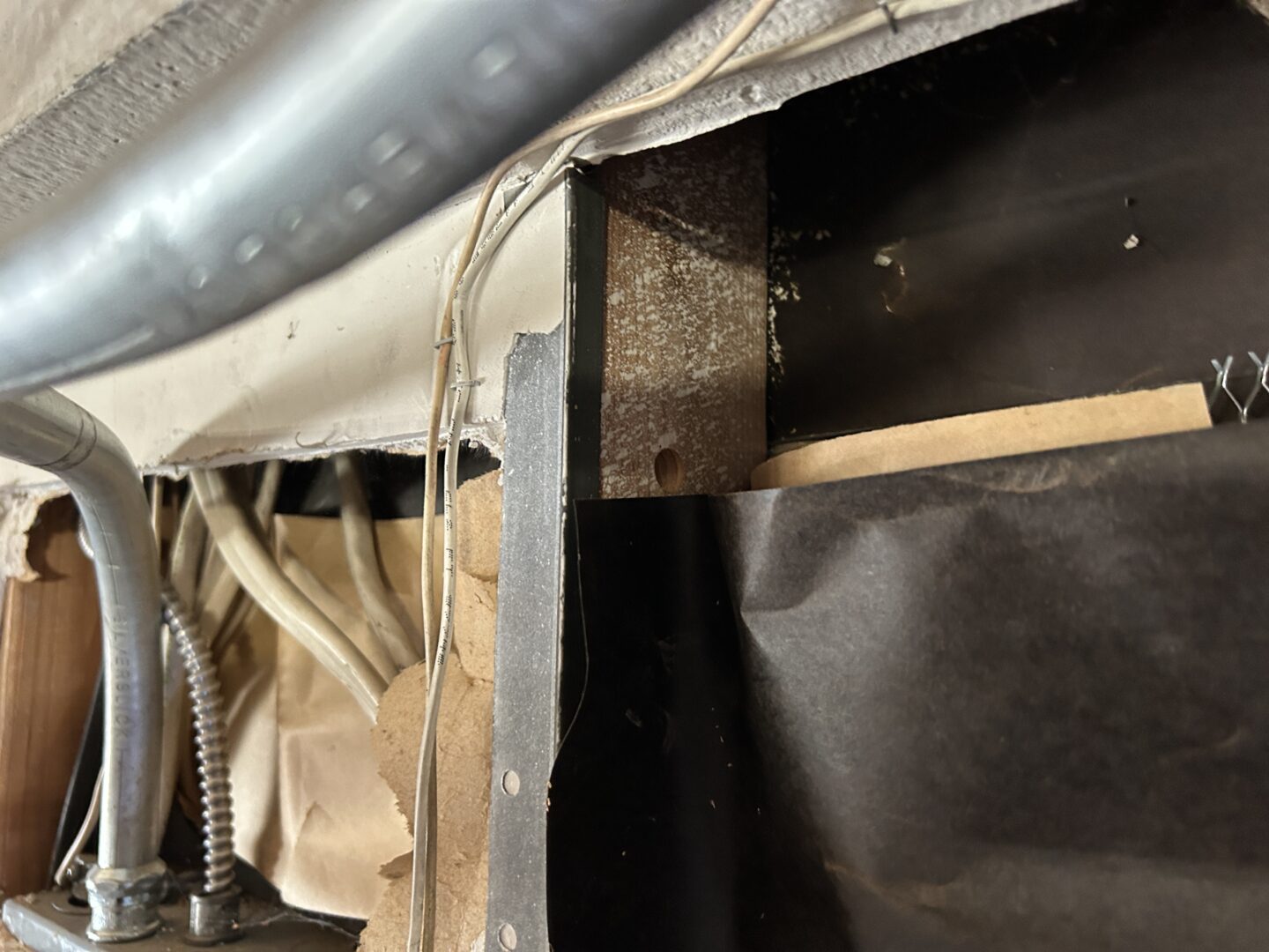
Also, look at how the new wiring will enter the fuse box. In my case, the fuse box is recessed into the wall, so the entry into the top, bottom, and sides of the box are accessible inside of the garage. Some service panels are mounted to the outside of the exterior wall, and in that case you should be prepared to bore out of the exterior wall in order to install (using a service entrance LB) into the top or bottom of the panel.
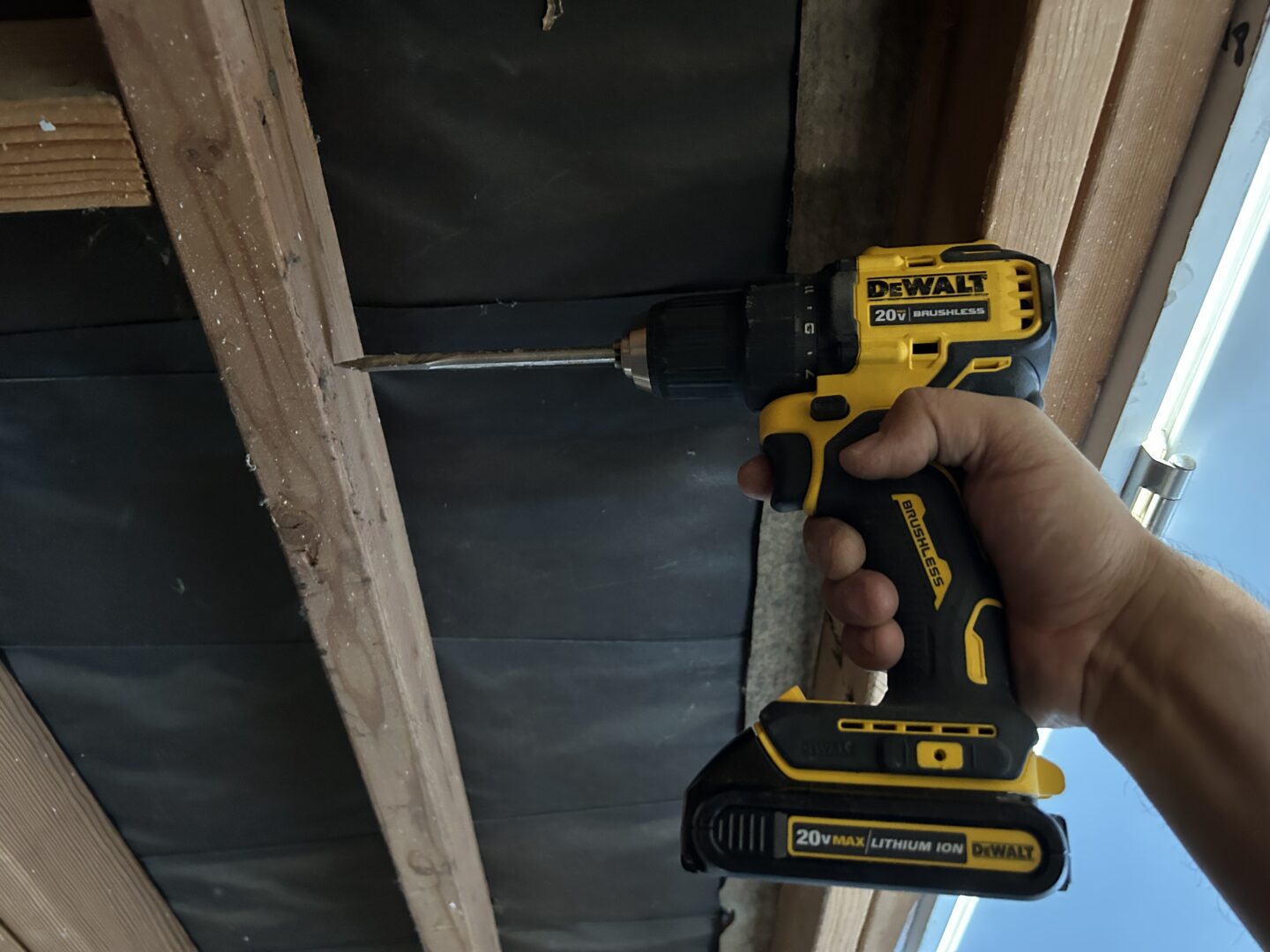
Since you have planned your route for the wiring, you can start drilling through the studs according to the hole and notch sizes as defined in your local codes and standards. I started off where the main panel was and drilled holes through the studs as I moved towards the proposed outlet locations. The best drill bits to use for drilling through 2x lumber are auger bits or spade bits.

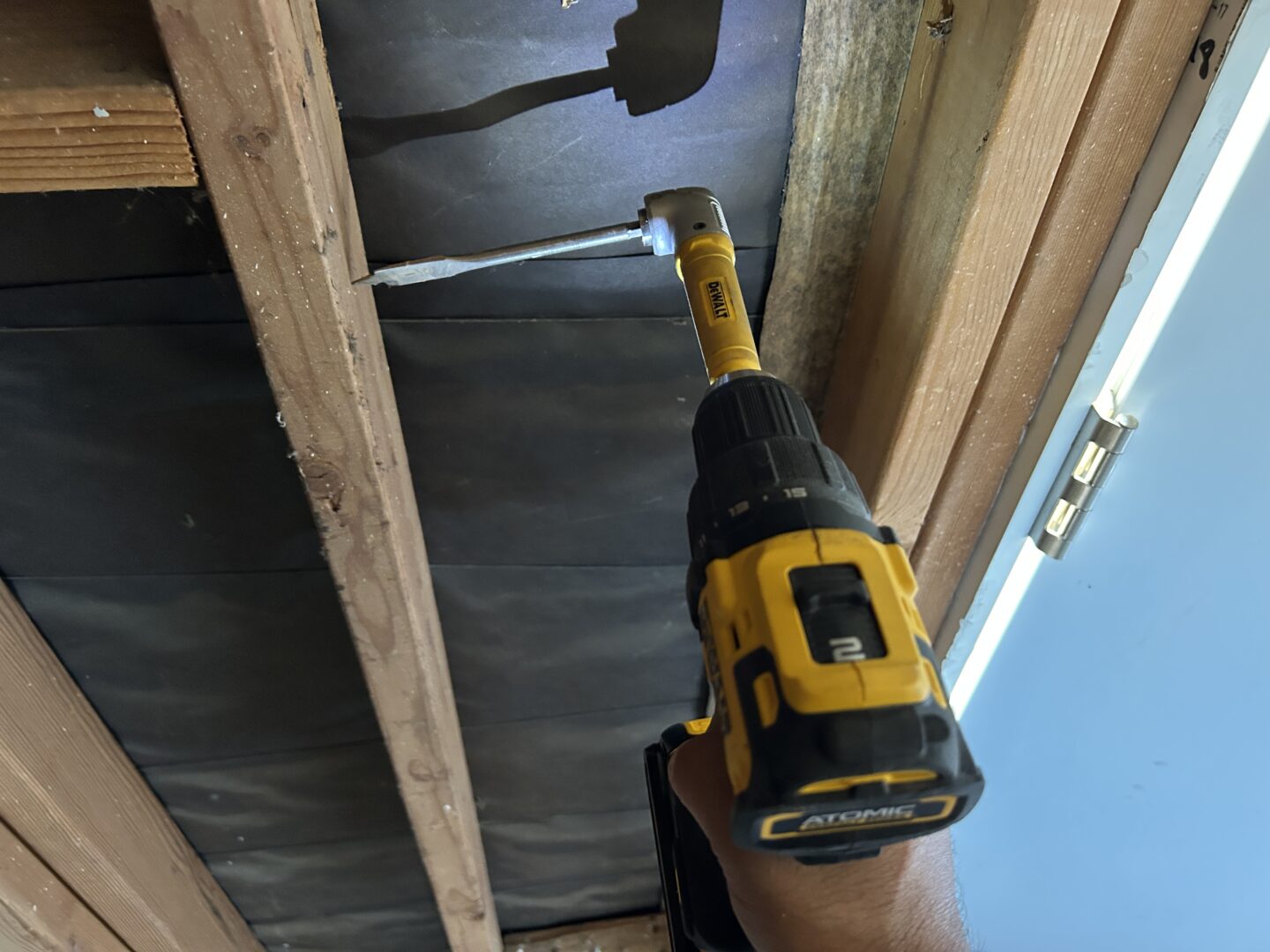
If you have some areas where you drill won’t fit, you’ll have to use a right angle drill attachment in order to drill through these studs.
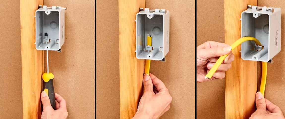
Installing outlet boxes where the outlets will be installed into is easy since the wall is unfinished. These “new construction” outlet boxes simply nail right into the side of the stud depending on where you want it. As for height requirements, again follow your local codes. Generally outlets are positioned 12″ off the floor and and just above counter height depending on where you plan to install.
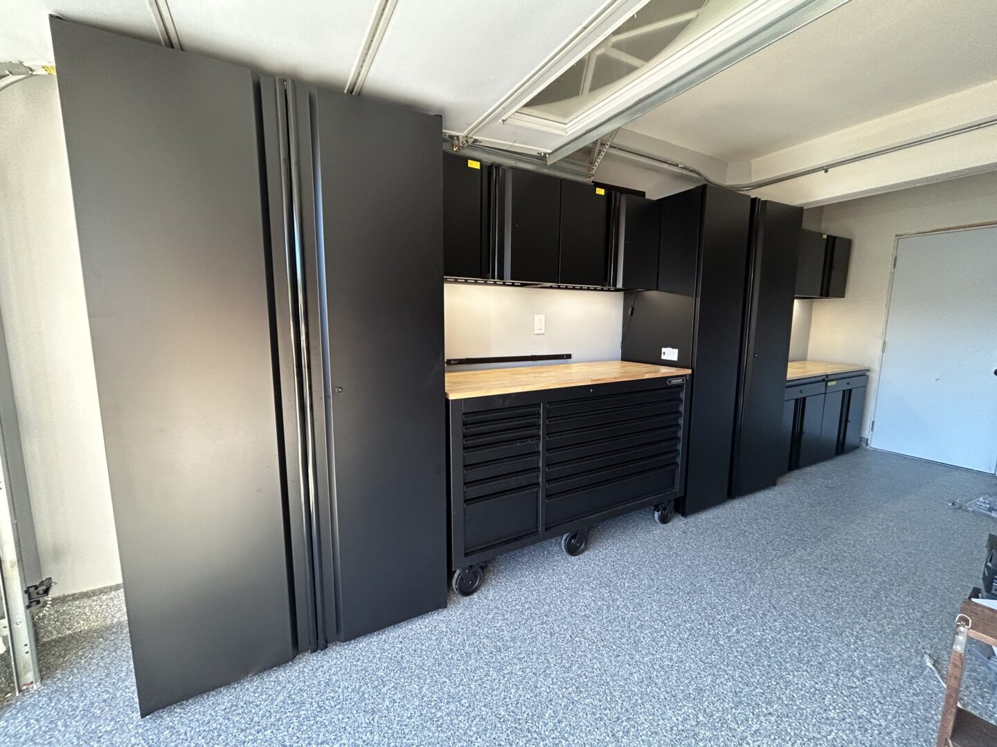
I installed my electrical boxes a couple inches higher than the expected counter height of my Husky Garage Storage Cabinets that were coming in. I also measured out where the workbench areas would be situated, so that I knew where they’d need to be installed.
Electrical boxes shouldn’t be installed flush with the studs because you still have 1/2″ drywall that will be installed, therefore you need to account for this. Luckily these boxes haves these little lines that show you where to set your box prior to nailing them in. The lines are 1/2″ markings so the line should butt right up to the front of the stud. Use a hammer to drive the mounting nails in through the side of the stud.

After all the boxes are secured to the studs, you may start running the cable from termination point to termination point. This means running the cable from the panel to the next outlet box, and then from box-to-box. When you get to each box, you will punch out the little cutouts depending on whether you’re coming in from the top or bottom and run the wiring through it. Make sure you leave a decent length of cable coming out of the box at each termination point so that you can have extra wiring that can be tucked into the boxes.
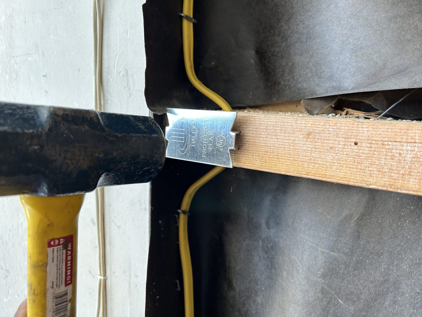
The cable is normally nailed to the studs along their runs. The nails should also be located within 12 inches of each termination point. Also, if the wiring runs through a stud, it must have a stud plate installed (hammered into the face of the stud or fireblock.) This prevents anyone in the future trying to drill into the studs and accidentally drilling through the cable.

Now, you can go to each box and cut the cable ends coming out of each box to about a 1 foot in length and fold it it over to tuck it into the box. These wires should be tucked in this way so that they are out of the way during the subsequent stages of insulation and drywall installation.

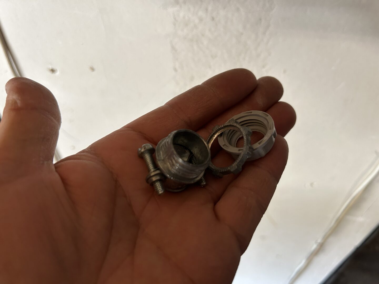
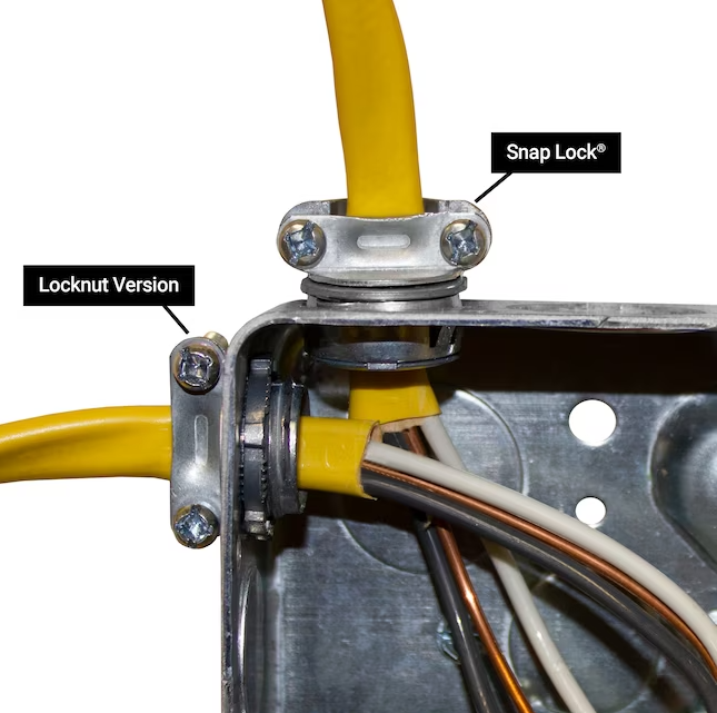
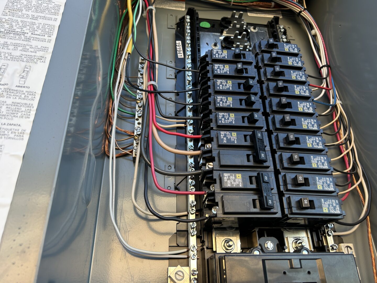
At the main panel, you’ll need to punch one of the precut openings out and install a correctly sized wire clamp connector as shown. This ensures that the cable is secure to the panel and cannot be pulled out accidentally.
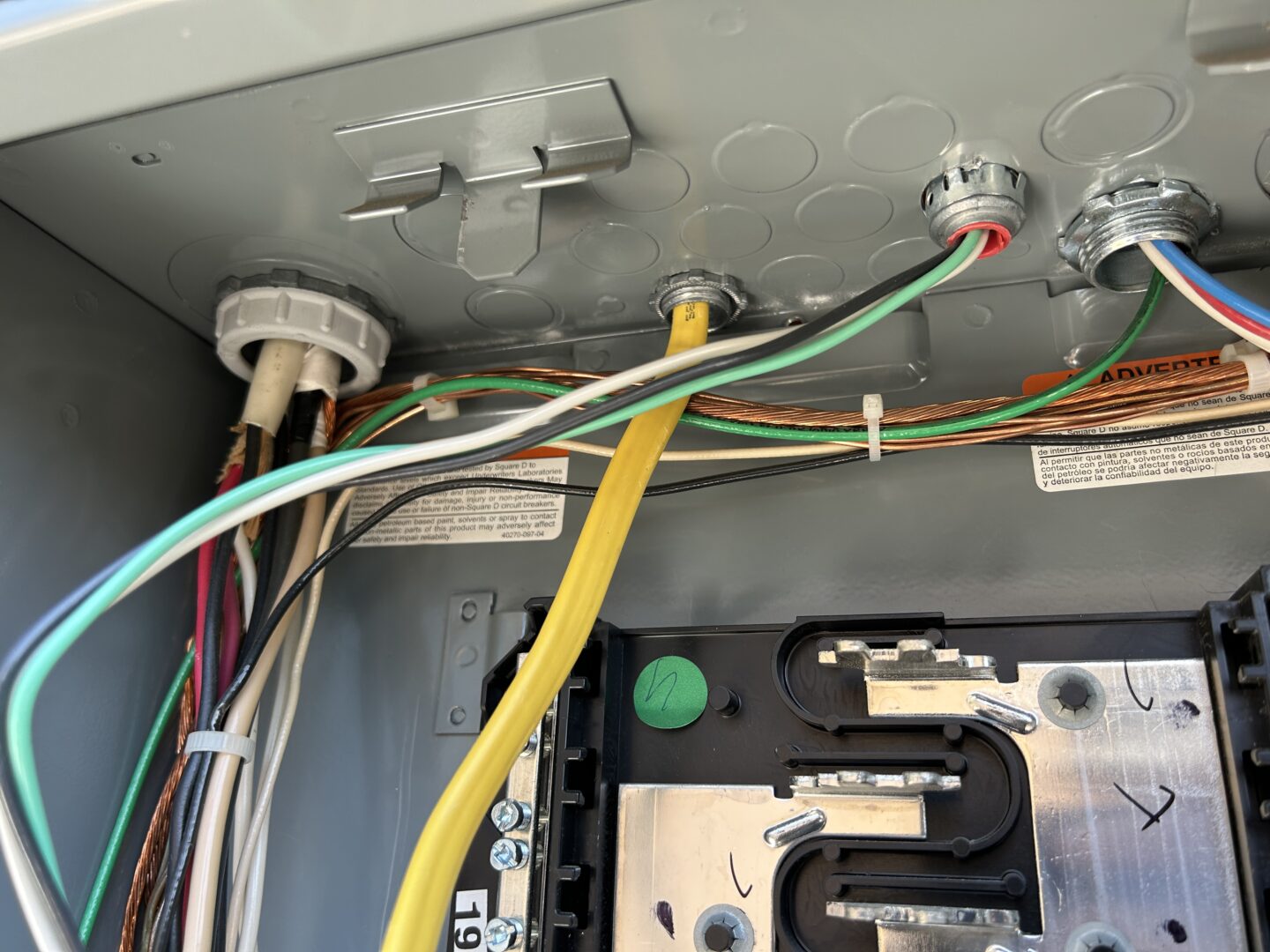
Prior to removing the panel cover, you must shut off the main breaker. When the panel cover is removed, you’ll be susceptible to electrical shock as the bus bars and wires will be fully exposed and energized. Run enough cable through the wire clamp connector so that you have the cable running twice the length of your electrical panel. This ensures that you have enough length to neatly tuck away the wires when you run each wire to their respective termination points.
I chose to leave the pigtail at the panel for now. After the insulation and drywall is installed, I will then connect the wires at the outlets prior to finishing the install at the panel side. This will allow me to connect the cables to each outlet box without worry that they are energized. At the panel, I push the new cable out of the way to the side and tape the exposed end well with electrical tape.

Installing New Electrical Outlets
Double-check that all wiring is run properly, stapled to the studs with proper spacing and at the correct locations, stud plates nailed at all required locations, and enough length of cable coming out of each outlet box. The cable ends should be folded up and pushed into each of the receptacle boxes. I also used fire blocking material to fill the voids where the wiring runs through the openings in the studs and fire blocks.
Basically at this point, the wiring should be completely run, so there’s no need to do any more work on the electirical behind the drywall anymore. The next step would be to install insulation (if applicable) and to install drywall.
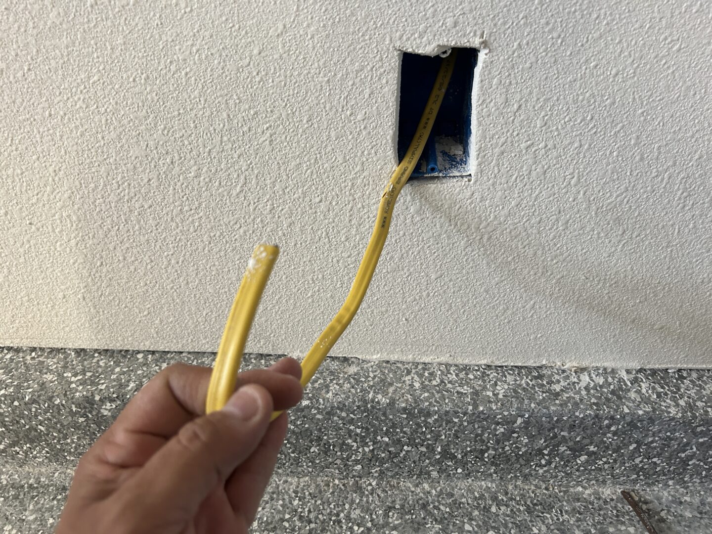
Skipping ahead, the insulation/drywall stage has been completed and now you’re going to continue with the outlet installs. At this time, we will now connect all of the outlets inside of the shop. Keep in mind that the cable that was run was not connected at the panel side, therefore the cables running to each outlet box should not be energized. As a safeguard, you can double-check with a multimeter or voltage tester.
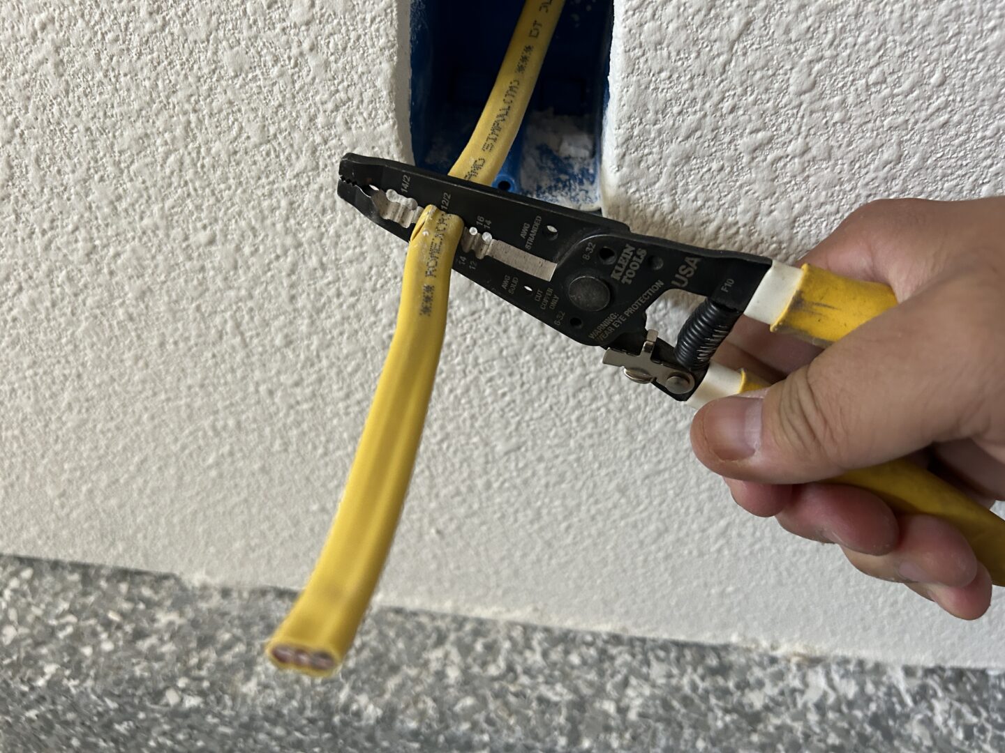
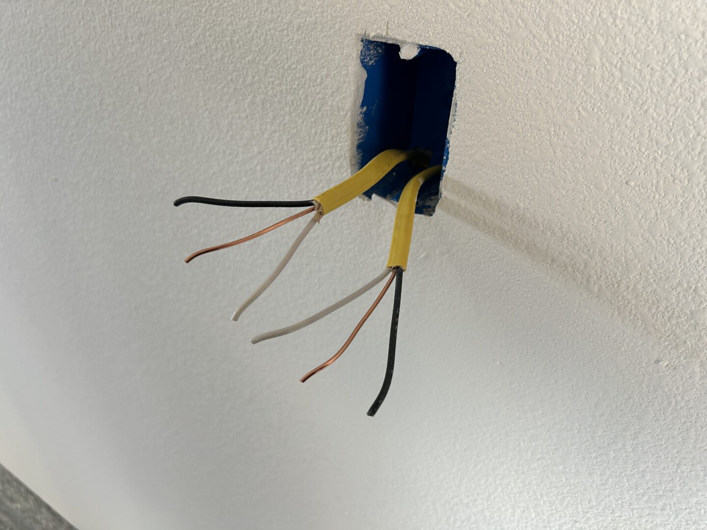
Pull the electrical cable out of each outlet box and strip off the main jacket. Then strip off the insulation for the very ends of the hot (black) and neutral (white) wires in preparation of connecting them to the outlet.
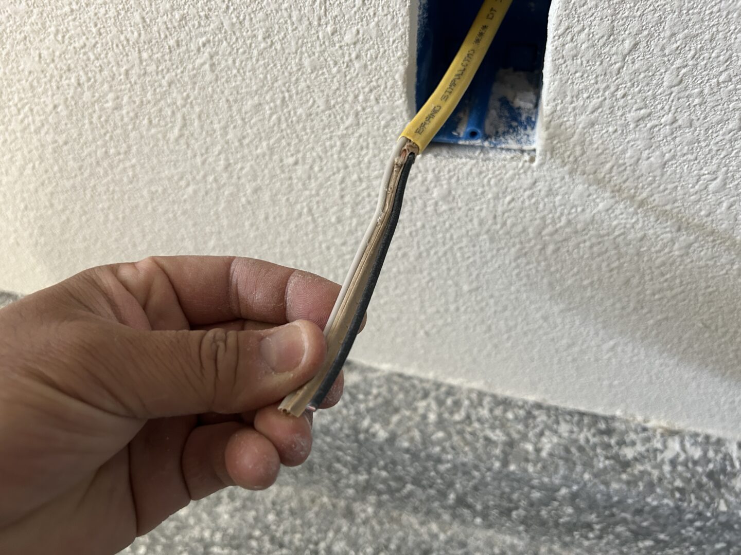
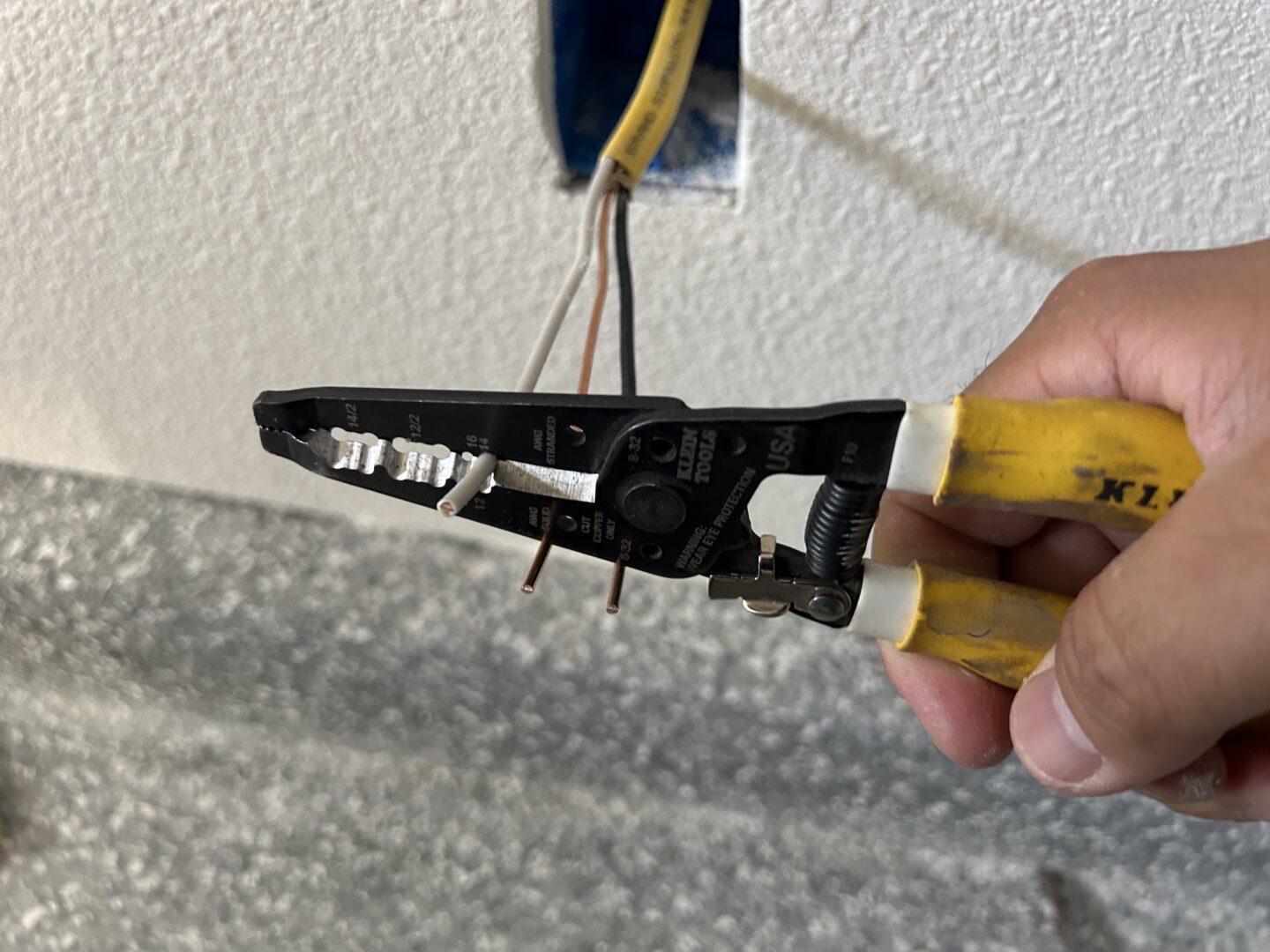
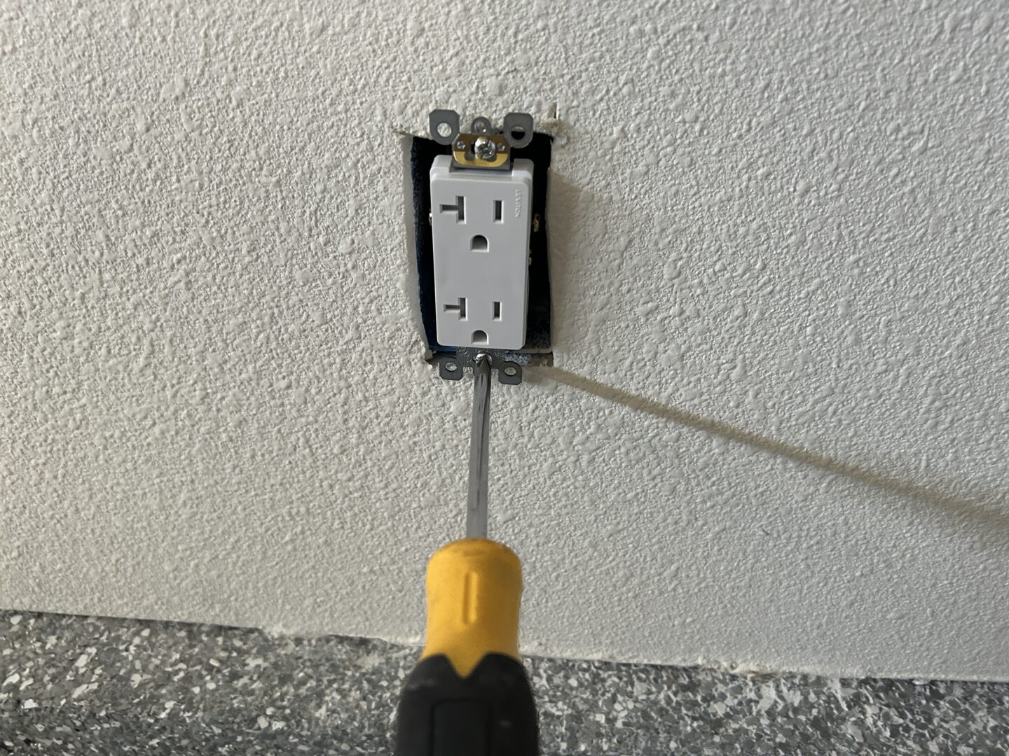
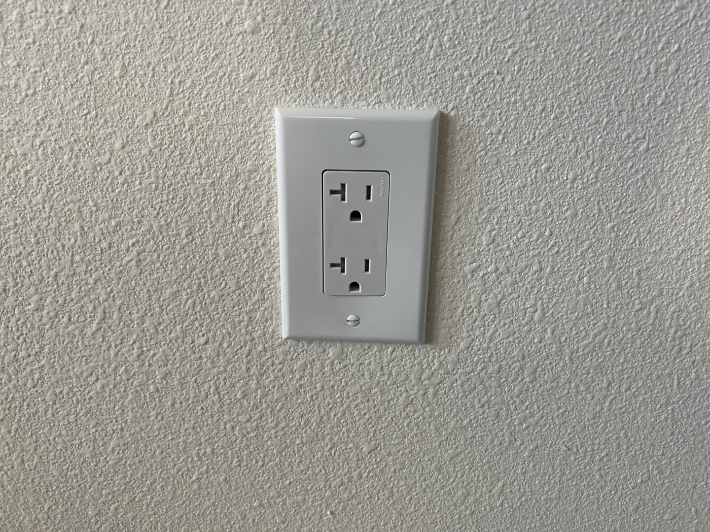
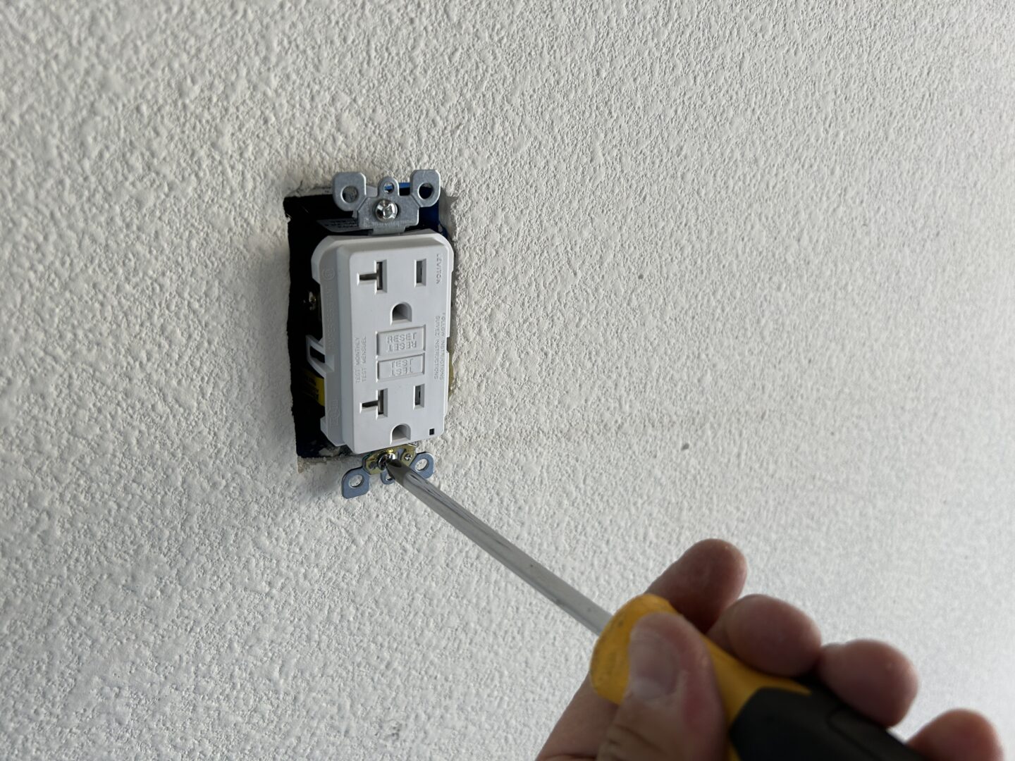
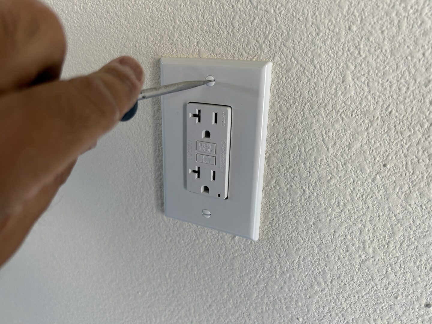
White is neutral, black is hot, and the bare copper wire is ground. Ensure that the tips of the hot and neutral wires are exposed just enough so that it provides contact for the receptacle. You want the wires to have enough conductor exposed to connect to the leads of the outlet, however you don’t want any extra exposed conductor (too much insulation stripped away.) Fold up the wires behind the receptacle, press the outlet in and screw it in with a Phillips head screwdriver, and install the outlet wall plate with Phillips head screws.
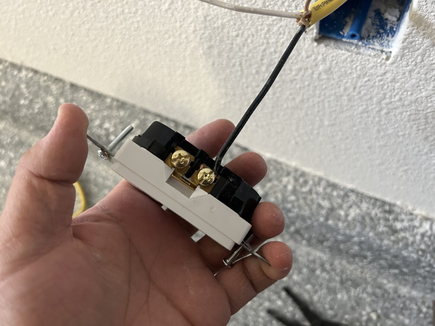
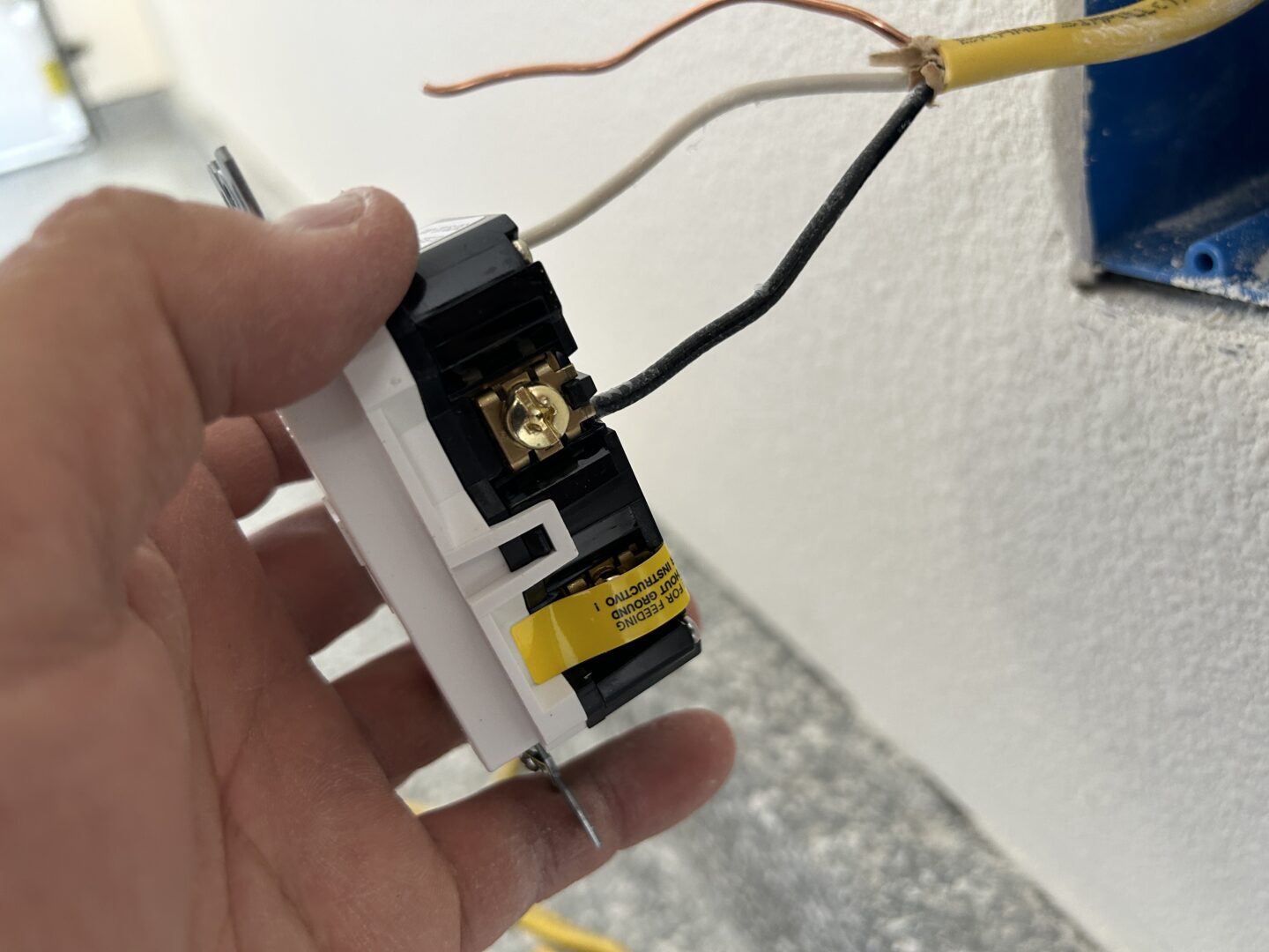
The outlet below shows the wiring at an outlet that is at the end of line. Therefore, there is only one set of wires coming in that need to connect to the electrical outlet.

When you have an outlet along your circuit where the feed comes in and out of the outlet location, you will have two sets of wires coming into the outlet box. As you can see below, this is the case. You can connect both hot wires and both neutral wires into each connection, however if you do not have the spots on the termination point to connect two wires, you will need to create pigtails. In the case of the ground wire, you will usually need to do this.
To make a pigtail, take some leftover wiring and strip off the outside insulating jacket if needed. You can then create pigtails using the black, white, or bare copper wires accordingly. The pigtail will be a short piece of wire where one side will be connected to the inbound and outbound wires with a wire screw tie, and the other end to the outlet. If you didn’t know already, you twist the wires together that you want to connect in a clockwise direction, then screw on the wire connector to secure it.


Wire up the remaining outlets until you’ve finished with all of the outlets you’ve planned to install.
With all of the outlets wired up, you will now go and connect the panel-side of the wiring. Again with the electrical panel, turn off the main power so that the panel is de-energized. When you take the panel cover off, you will now be able to install the new circuit breaker and connect the wiring for your new circuit.
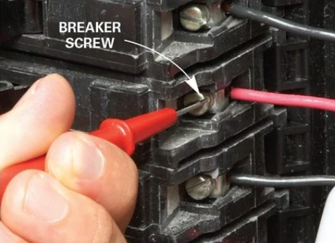
Remember that even if the electricity is shut off at the main power shut off, the line side of the switch is still hot (the side coming from the power company). With the main power shut off, your panel is de-energized so you can install the wiring to your neutral bus bar, ground bus bar, and new circuit breaker. Again, if you don’t know exactly what you’re doing here or you don’t feel comfortable working in the electrical panel, please hire a licensed electrician.
Cut enough of the wire so that it folds up nicely to the side of the panel. Then strip off the outside insulation jacket all the way back to a few inches coming into the panel. Run the wires in a neat fashion to each bus bar and breaker, and ensure that there is enough length to each wire so that there is no tension on the wires.
Strip off the very end of each wire and connect the ground wire to the ground bus bar, and the white wire (neutral) to the neutral bus bar. The black wire (hot) will be connected to a new circuit breaker that will be plugged into the hot bus bar.
You will need to knock out one of the slots on your panel cover so that the fuse is exposed in the panel cover window. Then, make notes on your panel so that you know what the new fuse is for.

I must stress yet again that if you aren’t comfortable working with electricity and/or are not familiar with your local electrical/building codes, please don’t attempt to do this work yourself as you can cause harm to yourself and potentially cause a fire if it is not installed correctly.
If you are familiar with local electrical/building codes and are comfortable working with electricity, this is a rewarding project to undertake yourself in order to save some money and to configure your electricity needs exactly how you want it.