When you make purchases through links on this site, The Track Ahead may earn an affiliate commission. Also, these posts are based off my own experiences. I am not responsible for any action you take as a result of reading this. Learn More
A big part of working on cars is making sure you have a good workspace. Whether you work on your car in your driveway or you have a two-car garage, it’s imperative to have good lighting. Even if you do work on your vehicle outside, you’re typically bringing parts to a workbench to work on certain parts. This is where good lighting comes into play.
My garage initially only had one light fixture, which consisted of a light switch that turned on a single lampholder bulb. An adapter was used to allow for two light bulbs to be attached for additional light.
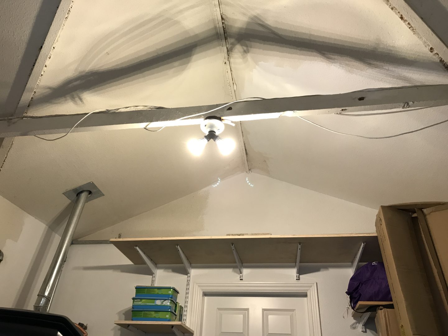
Although this lighting setup was okay for seeing in the garage, it simply wasn’t bright enough for all of the projects I do in my garage. The lighting is also coming from mainly one point source, so you always get shadows which can get annoying. I decided to extend the circuit and add some additional lampholders, which would provide more light output as well as spread the light out more evenly.
I wasn’t worried too much about the aesthetics, so I chose to go with simple lampholders that would hold a standard screw bulb since I have a stockpile of LED-style standard screw bulbs. After extending the circuit and plugging in the bulbs, I was able to produce much more lighting and see less shadows than I did before.
Materials & Tools Used
Leviton Porcelain Lampholder (Amazon)
These are devices that are used to hold light bulbs. They can be seen on almost any light fixture, but I used these as a standalone product that will simply allow for a standard bulb to be screwed in. I prefer porcelain over the cheaper plastic since porcelain is much more resistant to heat.
4″ Octagon Electrical Box (Amazon)
I wanted to use a box that would be large enough to fit wiring and act as a base for the lampholder. These 4″ octagonal electrical boxes worked perfectly for this purpose.
3/8″ Clamp Connectors (Amazon)
Clamp connectors are used to secure cables that enter and exit the electrical box. 3/8″ is a standard size that supports the flat cable.
12-2 Romex – 50′ Roll (Amazon)
12-gauge wire handles 20 amps. Typically, you’d only need a 14-gauge wire for solely lighting, but I wanted to have the option of adding an outlet down the line, so I opted to use 12-2 Romex cable (12-gauge, 1 hot wire, 1 neutral wire, and a ground wire).
Wire Stripper (Amazon)
A good wire stripping tool goes a long way. Any of these wire strippers will generally be able to strip standard gauge wires, but look for a well-reviewed, good quality one and it will last you a lifetime.
Construction Screws (Amazon) used to attach electrical boxes to joist
Many people use drywall screws to attach electrical boxes to joists and many times there will likely be no issue. However, drywall screws don’t take shear stresses as well as other types of screws like wood screws, decking screws, etc. Therefore, it is recommended to use strong screws to secure electrical boxes.
Hammer (Amazon)
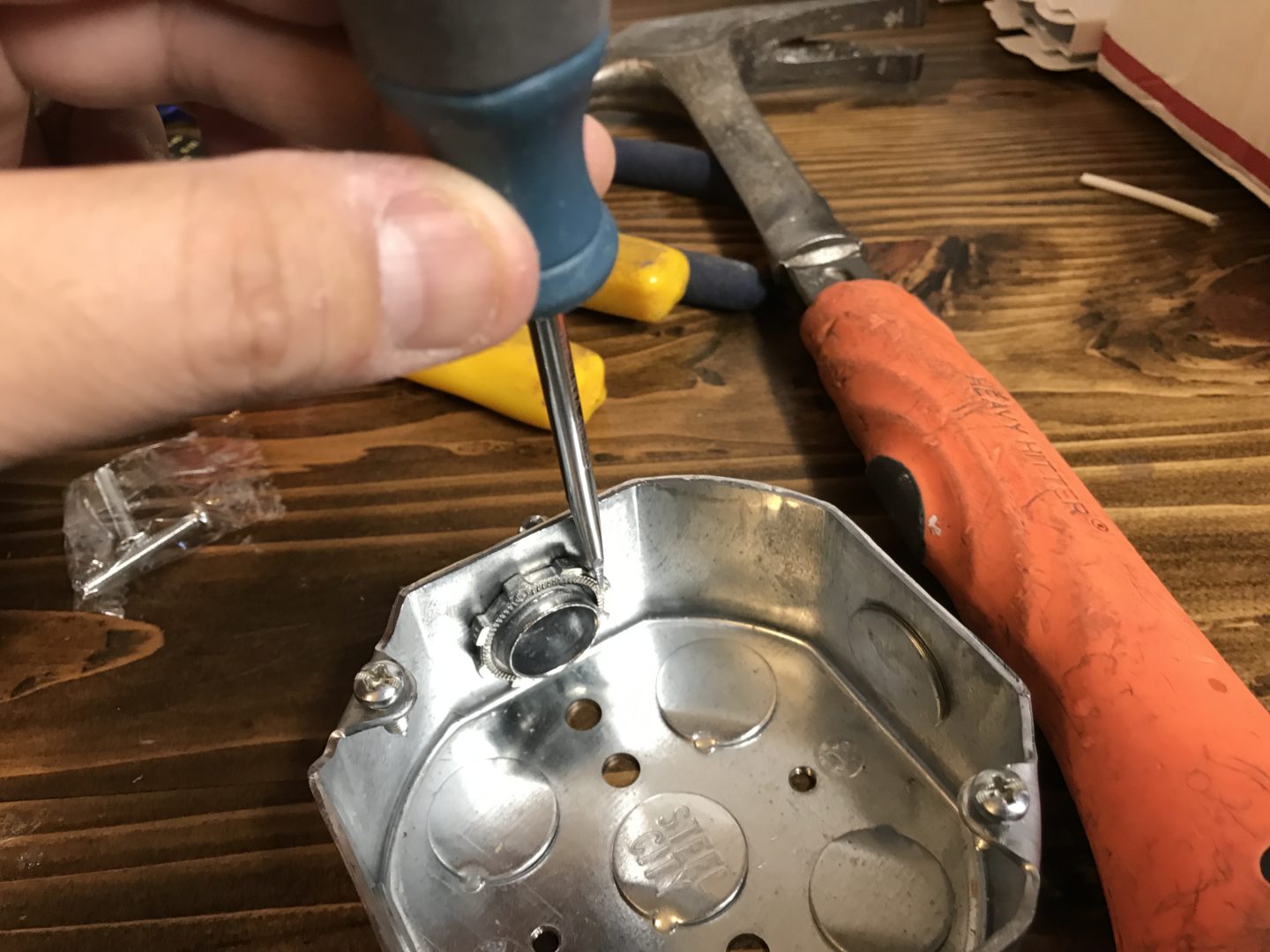
The hammer is used in conjunction with a flat head screwdriver to tighten the lock nut onto the clamp connector.
Screwdriver Set (Amazon)
Phillips head screwdriver does the heavy lifting with screwing in the Phillips head screws for tightening down the wires and hardware. The flat head screwdriver has a unique purpose of being used with the hammer to tighten the locknuts for the clamp connectors.
Planning the Run
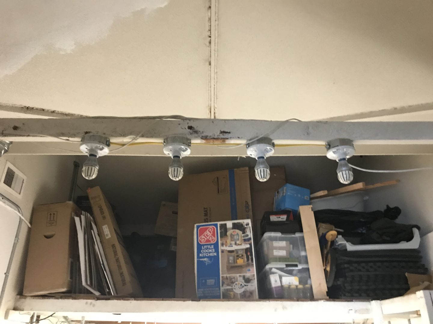
First, plan what you want to use and the route you plan to go. In my case, I have a 2×4 that spans the garage in which an existing single lampholder is mounted.
I needed only a short run of about 5 feet of 12-2 Romex and about 1 to 1-1/2 feet of the same cable between each lampholder. The new Romex would tie into the existing wiring I had, which was also a two-wire system.
The Lampholder Unit
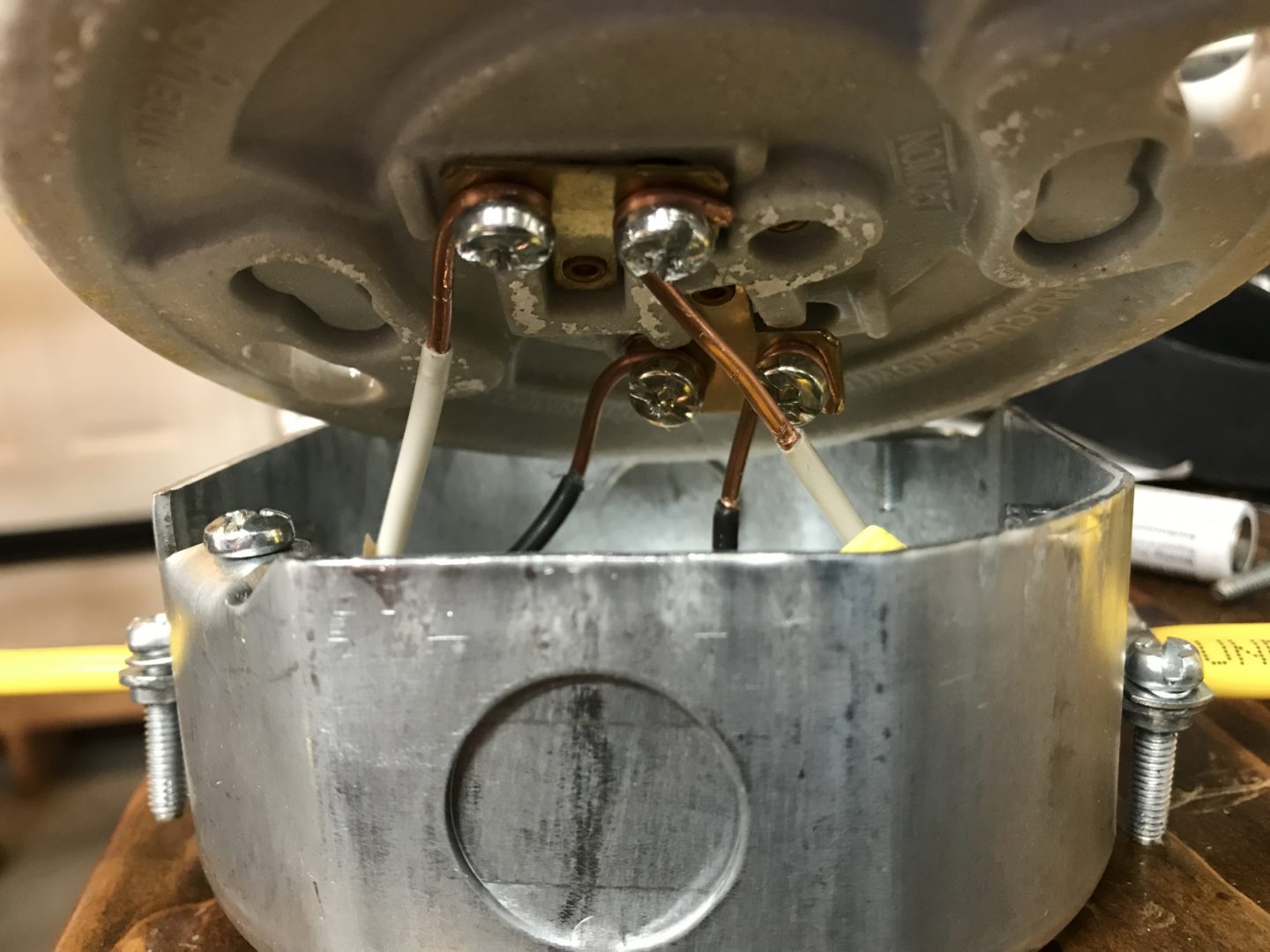
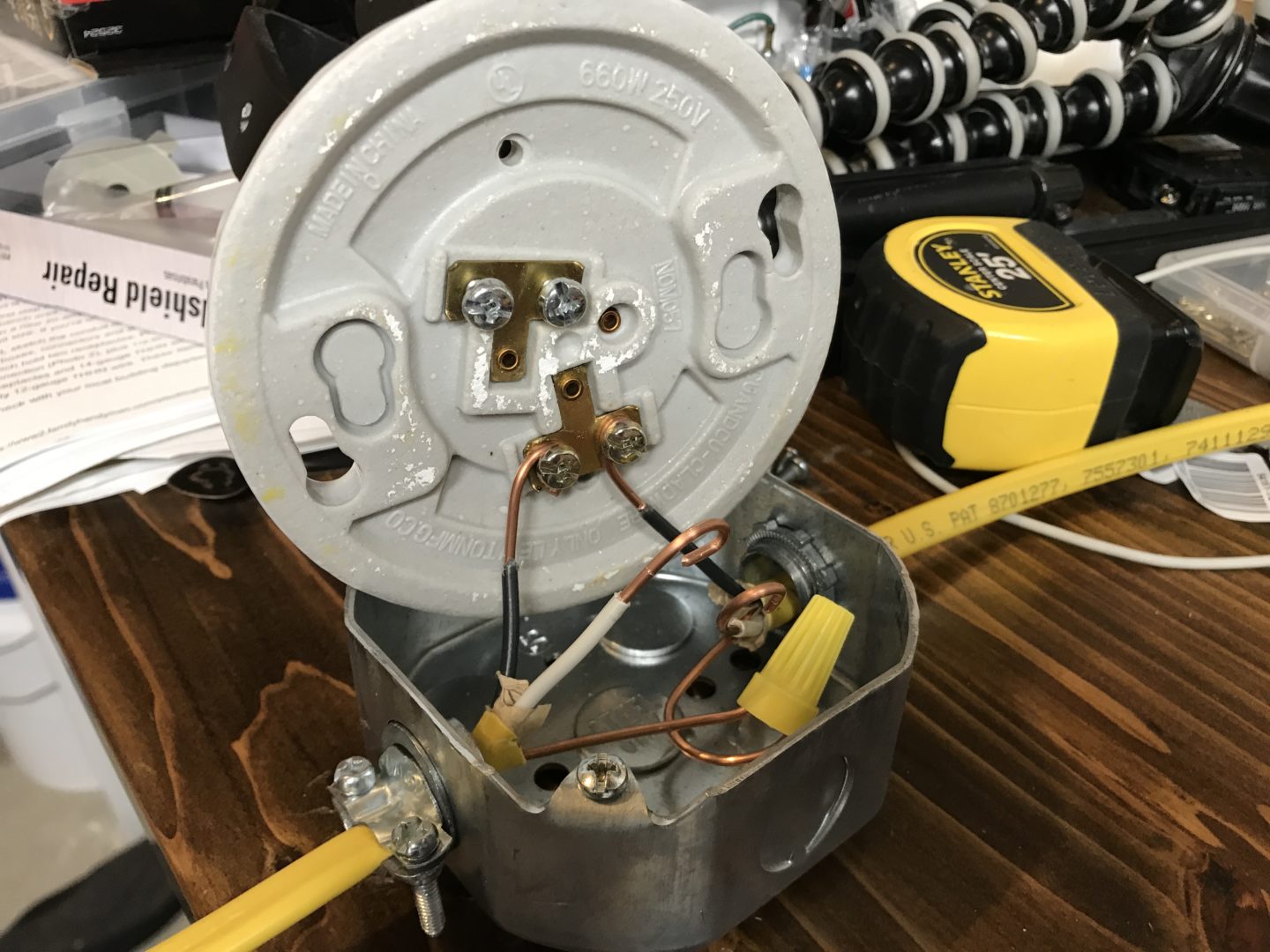
It’s important to know how the lampholder works and how to make the proper connections behind the lampholder. On the socket portion of the unit is where a standard light bulb plugs in. The side casing is the neutral connection for the bulb, while the center terminal is the hot connection.

When a light bulb is screwed into the lampholder, it is energized (and lights up) when the bulb is screwed entirely into the socket until the point the tip of the bulb makes contact with the hot contact in the center.
This design is imperative in keeping the public safe. When replacing a light bulb, the energized portion of the bulb is recessed and hidden away to prevent accidental contact by the person changing the bulb.
Keep in mind that if you are replacing a bulb and have never verified if a particular lampholder is wired incorrectly, you must proceed with caution. If the wiring was done incorrectly so that the hot and neutral wires were switched, then the socket becomes the energized portion and you have a hazard waiting for you at your fingertips. Obviously, if you test the existing lampholder with a multimeter and find that the wires are swapped, then the power will need to be switched off and the wire connections corrected.
On the backside of the lampholder, there are two T-shaped pins. Each one has a set of screws available for you to attach wires to. On the type of lampholder below, you’ll see that the T-shaped pin that points directly to the center is the hot terminal, which connects to the center button on the other side. The pin that is not pointed to the center, but off to the side, is the neutral terminal which connects to the socket on the other side.
Lampholders can look different depending on the manufacturer, but take a close look and you’ll be able to see which terminal connects to which. This is important to understand as you don’t want to mix up the polarities for safety sake.

Installing Wiring and Electrical Boxes
I haven’t shut off power yet as I’m simply installing the cables and boxes first. In an effort to minimize power shut-off time, I do everything I can until I need to tie in the wiring. At that point, I will shut down power and make the connections to the existing wiring.
If you want to connect all the wires and boxes together prior to mounting it, you can do so in order to minimize the amount of time working above your head and on a ladder. This will help minimize potential aches and pains the next day.
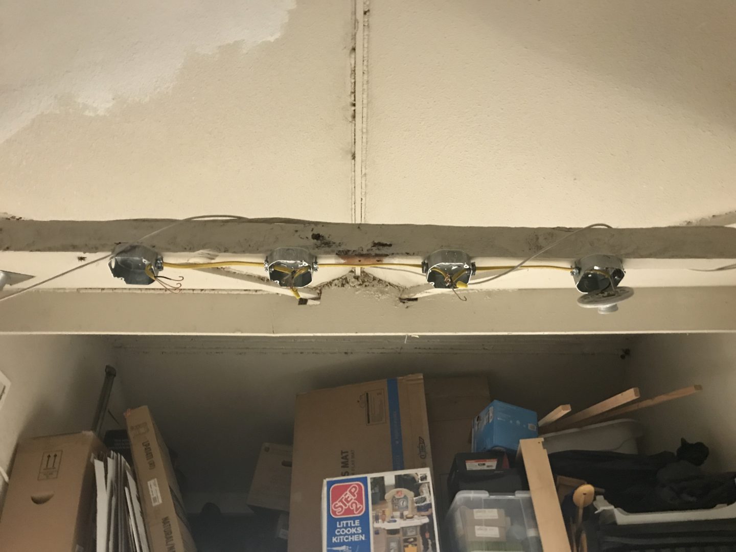
I started by mounting all the electrical boxes. I have a total of 4 boxes I needed to mount, spaced out evenly along this 2×4 close to the ceiling in the garage. When installing the boxes, place them up against a secure joist and screw in with screws. Drywall screws are not preferred as they don’t have much shear capacity. You want electrical connections to always be secure, so use wood screws, decking screws, etc.
Install all the clamp connectors to the electrical boxes. Use your screwdriver or chisel and pop out the knockouts where the wires will enter and exit. I had 3 boxes that needed knockouts removed on two sides and the last box (dead-end of the wiring) with a knockout on one side removed.
Remove the provided locknut from the clamp connector and insert the connector into the electrical box. Then use the locknut to tighten from the inside of the box as far as you can by hand. Then, use a flat head screwdriver pressed up against one of the ridges of the locknut and hit it with a hammer to drive the locknut tight.


Route the Romex cable through each box and allow a few inches of Romex to enter the box. The wiring clamp can be tightened down to secure the cable. The few inches that are left inside of the box can be stripped back. Cut the yellow jacket back, exposing the black (neutral) and white (hot) wire.
Strip the black and white jacketing back so that there is only enough to curl up around the lead screws. In the photo below, too much of the black/white jacketing was stripped back; there should only be enough of the actual wire exposed to curl around (use long-nose pliers) for the screws.
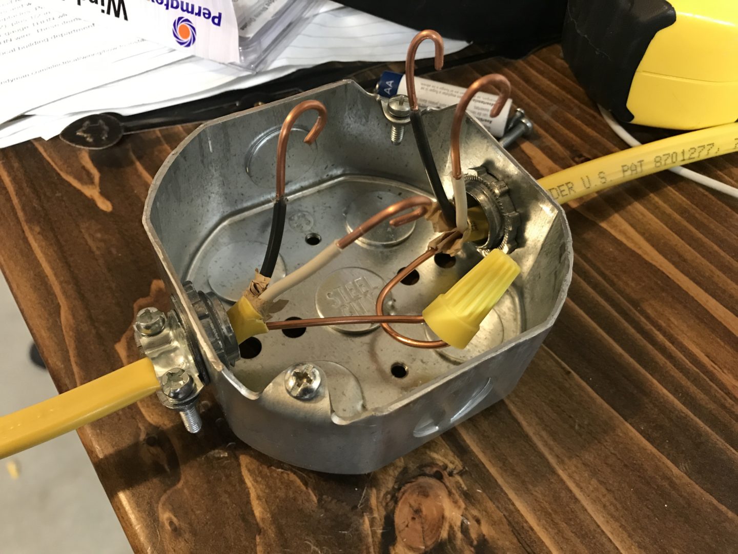
For the ground, you’ll want to tie them all together with twist-on wire connectors. For the electrical boxes that have entering and exiting wires, there will be connections on all leads.
For the electrical box that is at the end, there will only be wiring entering one side. This dead-end box will only have one side of the box punched out.

With all the electrical boxes secure, cable clamps tightened down, all wiring connected, I just needed to do the tie-in to the existing wiring I had. I shut down the main panel, tested to double-check there was no power going to the location I was working in, and made the tie-in.
Because I was tying into the existing wiring, I made the connection to the existing wiring within the first box. If I had to make a tie-in further down the line, I would have to make that connection in a dedicated box, then run wiring to the lights.
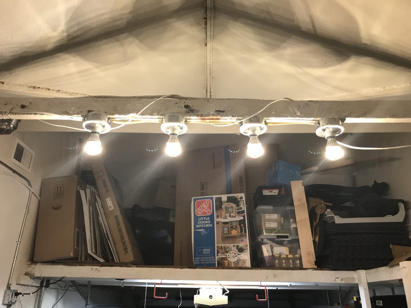
Here is the finished product. The spiraling wire is not part of the system; it’s an ethernet cable that was left wrapped around the joist. The lighting has really brightened up the space and made it easier to work on things in the garage. The next step will be to add some dedicated lighting on my workbench for better visibility when working directly on the bench.


2 Comments
Umm, wait? No positive/negative with AC…
I haven’t looked at this post in years, but I’m glad you brought this up! You are right, I removed this from my post. Thank you.